PlutoLink
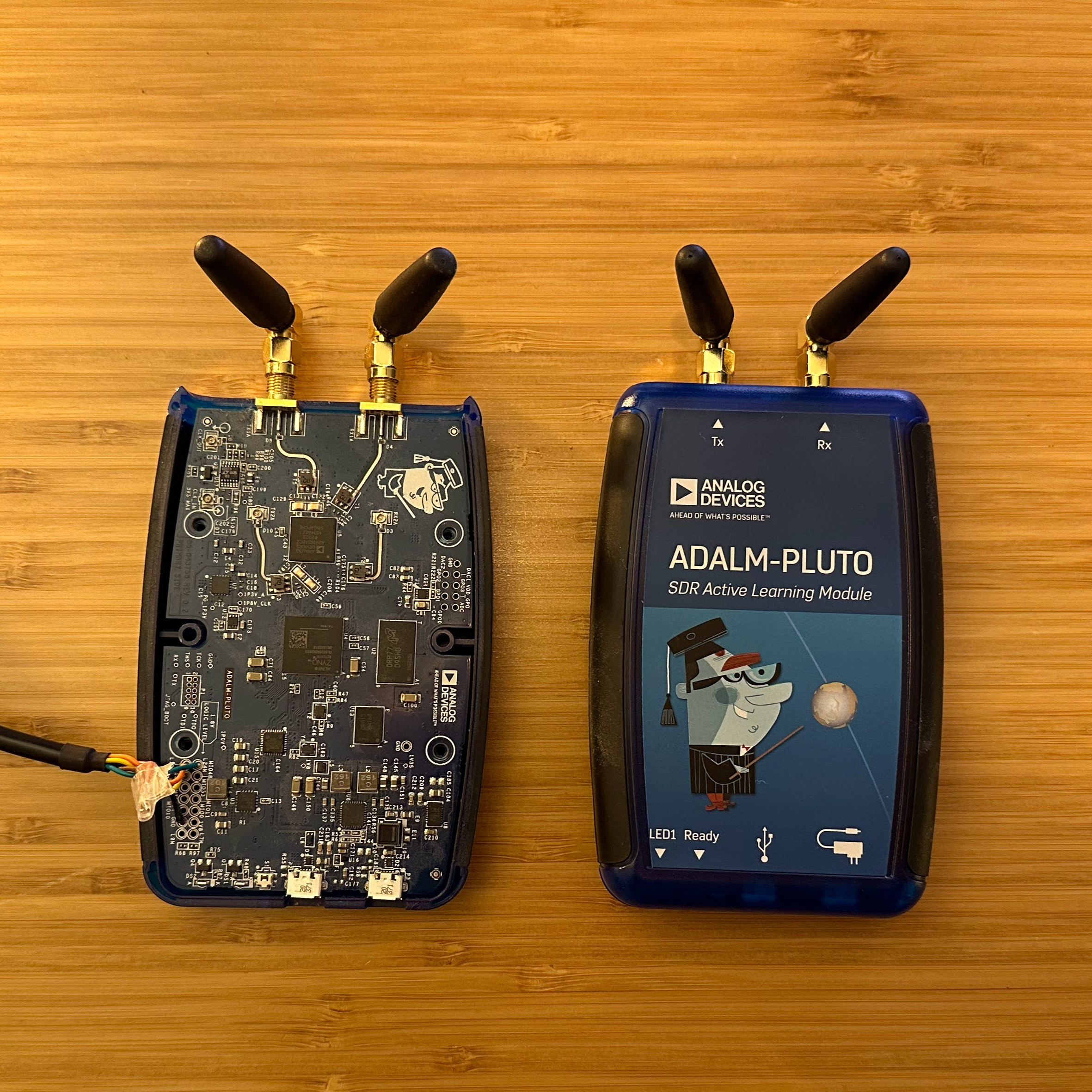
PlutoLink is a simple RF transceiver implementation using the ADALM-PLUTO RF Learning Module. The host-side interface is UART-compatible and two PlutoLink setups can be used to form a simple link between MCUs.
The RF processing is done exclusively in the Zynq FPGA fabric and is designed to be portable to other non-Zynq FPGAs. The Zynq ARM core is used exclusively for radio management and debug support. TX and RX can occur theoretically anywhere in the 325 MHz to 3.8 GHz range that is supported by the module, but operation is expected to be done by licensed HAMs in one of the allowable bands (probably >2GHz).
This is a proof-of-concept project that is intended to explore the use of the AD9361 RF transceiver with FPGAs to build low-power and low-cost transceiver modules for use in Cubesats. The Zynq will be replaced in actual cubesats with a low-cost FPGA (probably a Spartan or equivalent) and a low-power microcontroller (probably a simple Cortex-M0).
The project is available in GitHub: https://github.com/trswany/plutolink. Many of the HDL modules are in a separate GitHub "rfkit" project: https://github.com/trswany/rfkit
SensorForge
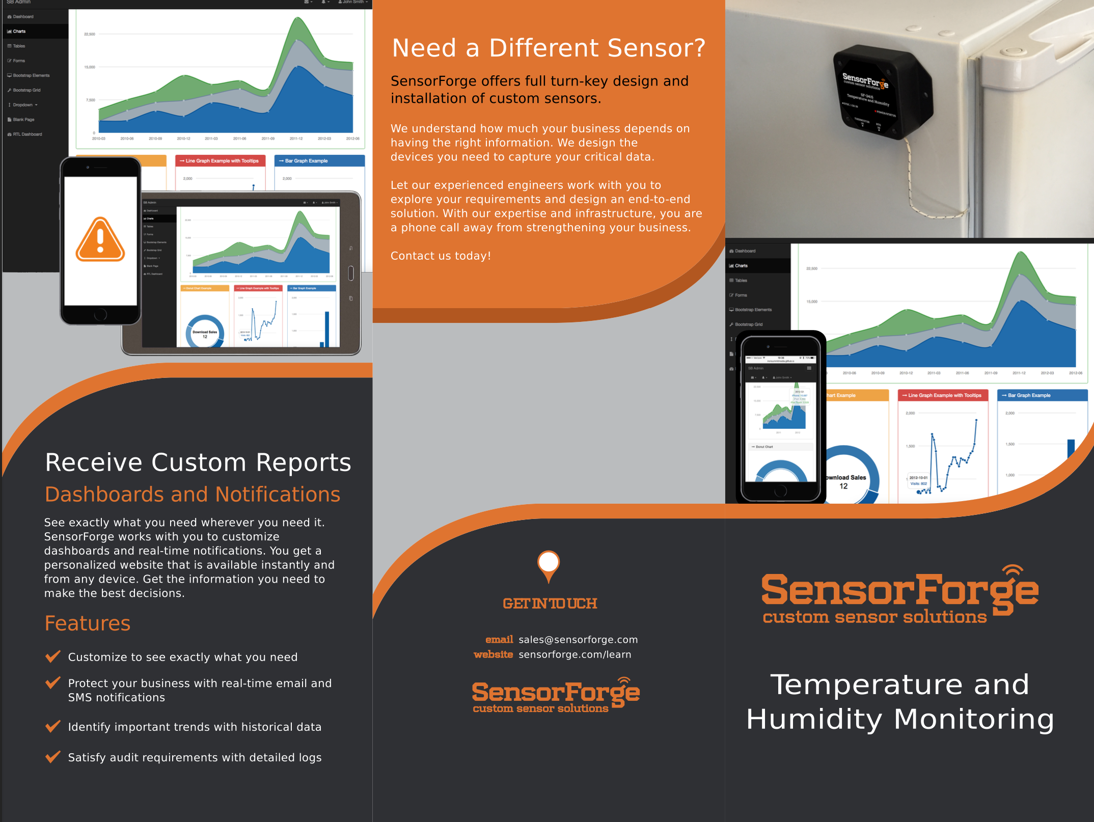
In late 2015, I and 3 co-founders started researching opportunities for cloud-connected IoT sensor solutions. We developed an intitial proof-of-concept: a wifi-connected industrial temperature and humidity sensor. We were exploring new IoT and web-application technologies that we can leverage, and we were developing processes that will allow us to quickly and efficiently deploy new custom sensor solutions. Our goal was to improve our customers' efficiencies and decision-making processes by providing them with the field data they needed.
We built the hardware, deployed some cloud systems, created marketing materials, and then started looking for customers. We got the most interest from breweries; they were interested in cloud-connected sensing to monitor their fermentation process. We visited several breweries and tasted lots of free beer.
We got lots of high-level interest, but we didn't find a customer with enough commitment to drive development of new hardware. I also took a job at Google and moved to California, so we decided to wind down the project.
KickSize
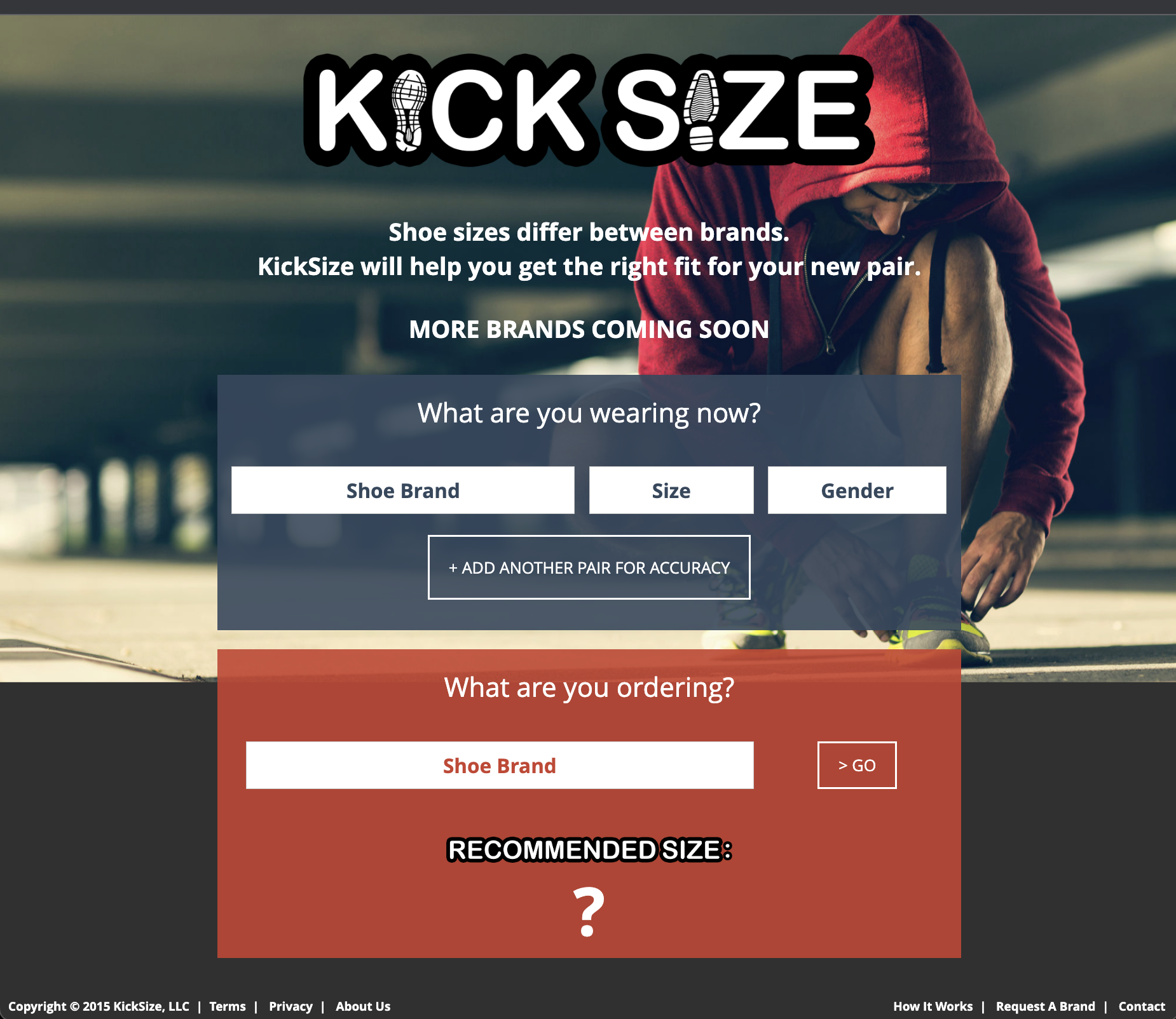
In 2015, I and 2 co-founders developed an online shoe-sizing service to improve the online shoe-buying experience. I was the software developer, and the co-founders helped with business and sales. We researched shoe sizes, gathered shoe data, and created an algorithm that recommended a shoe size based on the sizes of a customer's existing shoes. The initial project was a simple website that called into a linear regression model. As we collected more data from customers/users, we would rebuild the linear regression with the goal of having it become more accurate over time.
We shopped the solution around and tried to sell API access to our model. We quickly learned that the customers weren't tech-savvy enough to use the API, and would instead require a turnkey solution that integrated into their ecommerce website. We found a customer and created a Magento plugin; I had never heard of Magento but was able to whip up a simple plugin in about a week. The customer used our plugin for several months and we turned a small profit on the business overall.
We had trouble selling our product into the small shoe sales market because the customers there weren't convinced that sizing was a problem. We also saw that we were going to have trouble with larger customers (Zappos, Amazon, etc) because they were already starting to deploy their own sizing tools. After several months, we decided to wind down the project and try something new.
Best RS232 Breakout Board
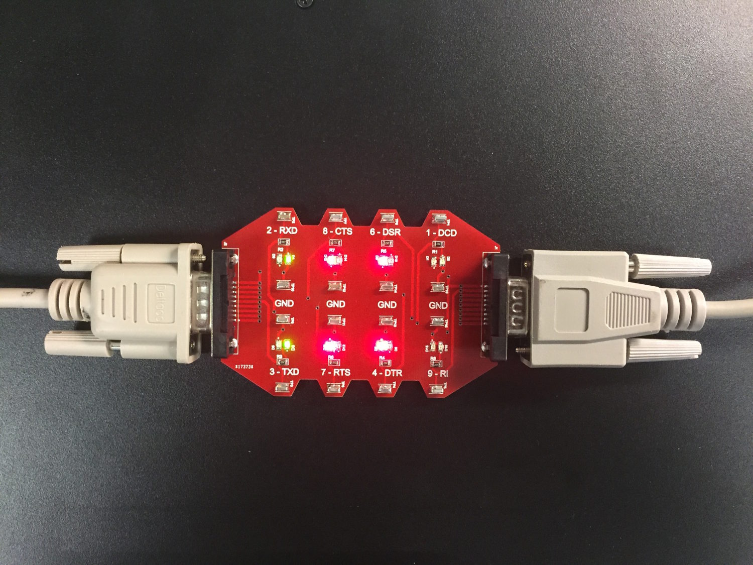
While working in 2015, I became frustrated with the lack of good RS232 breakout boards. All I needed was something that lit up, was clearly labeled, and provided good test points for my oscilloscope.
RS232 signals are poorly named, different devices use the signals differently, and there are several communications settings that need to be configured. If you get anything wrong, it just doesn't work; you don't get any clues about what needs to be fixed. At OSI, we worked with a lot of legacy field equipment and we often need to break into the signal and get some clues about how to get the systems communicating.
I used upverter.com for schematic capture and PCB layout. They have a great "parts concierge" service that will create symbols and footprints for you automatically. I put in a request for three symbols/footprints, went to a 1/2 hour meeting, and had the parts ready for me when I got back. I ordered a 10-pack of PCBs from dirtyPCBs.com for only $25. I got the boards in a few weeks, and they looked great.
The board worked great; I could probe the signals easily. It has plenty of ground test loops to attach the grounding alligator clips. The lights are sometimes hard to read at higher baud rates with single-character messages, but that is expected. There is still enough of a flicker at 115200 to let you know that a character was sent.
The project design files (schematic, layout, BOM) are available on Upverter here: https://upverter.com/design/trswany@/rs232-breakout-board/
ModularIO
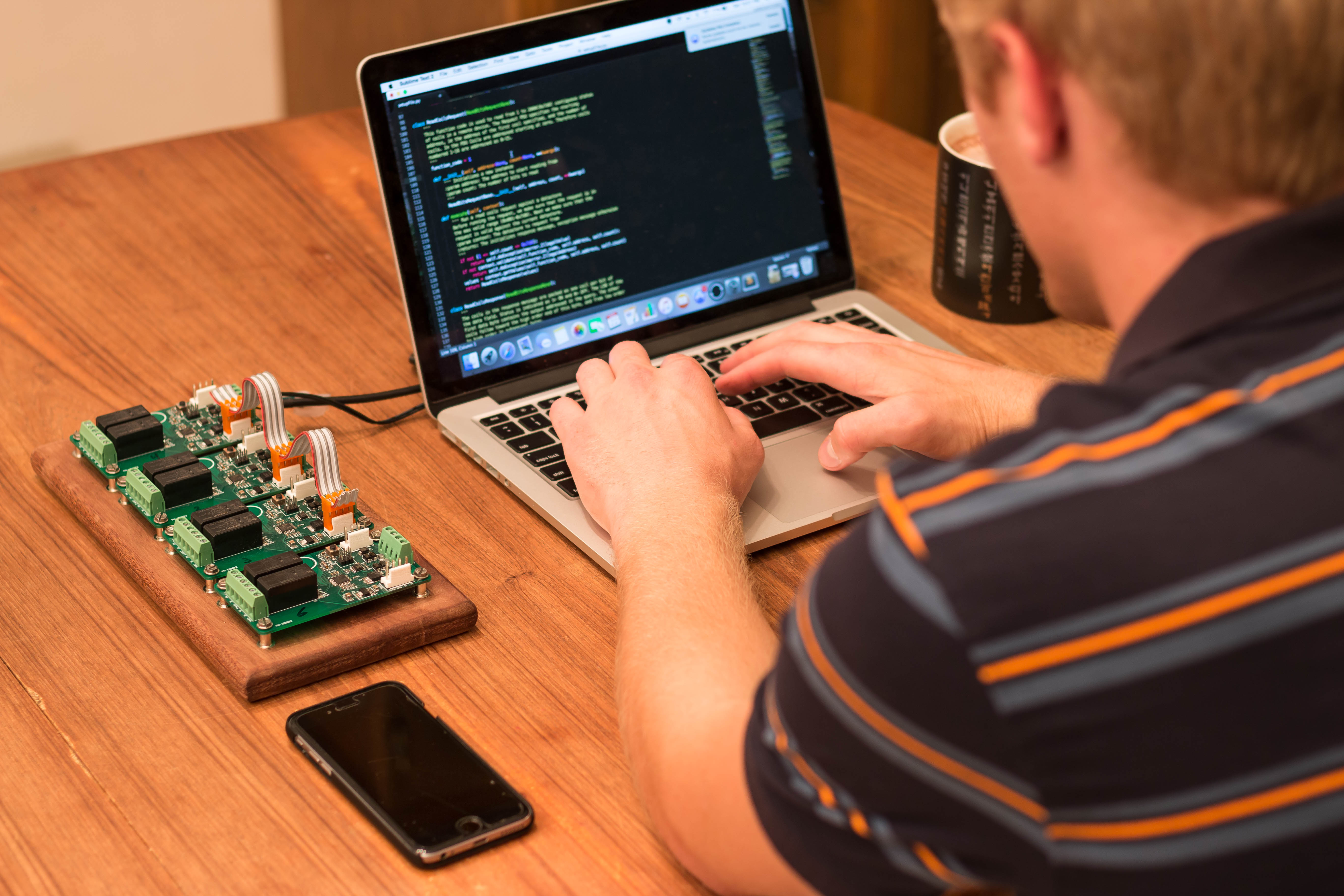
In 2015, my dad, my brother, and I became interested in simple IO modules that could be used for testing or remote IO. There are many IO modules on the market, but many of them are overly complicated and expensive.
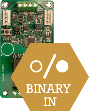
We started by building two simple modules, a relay-output module and a binary-input module. Our plan was to build open-source libraries for popular programming languages (starting with Python) to make these modules simple to use. The modules could be used with popular development boards, including Raspberry Pi and Beaglebone Black.
The modules used an RS485 bus and an FTDI USB-to-RS485 converter to communicate with the host PC. The
The hardest part of this project turned out to be creating a standalone bootloader that could jump into a second main application. It doesn't work to simply jump to the correct memory address. The ARM processor and peripherals need to be reset to their initial states, the vector table needs to be remapped, and the stack pointer needs to be set to its new "initial" value.
We got both of the new modules up and running, and we have been using the relay-output modules to toggle Christmas lights at our parents house.
This project has been put on pause for the moment. I was researching methods of driving traffic to our website, but I wasn't able to find a good way to connect with potential customers or drive purchases.
Traction Control for RC Car
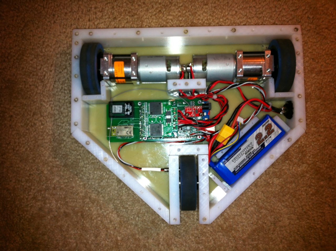
For my senior design project, our group was told to create a traction-control system. We were given flexibility in choosing an implementation. Since we had a mechanical engineer on our team, we decided to build a remote-controlled car with electric motors.
Our project consisted of four technical aspects: mechanical design and chassis wiring of the RC car, a controller PCB, firmware for the controller PCB, and a desktop application to view telemetry data. I was responsible for the controller software as well as the desktop application.
Mechanical Design and Chassis Wiring: We settled on a “home plate” shape for the robot after we decided on a three-wheeled vehicle design. This allowed for a couple angled sides and the rest of everything at right angles, making fabrication very simple. The three-wheeled design was important since we want the rear wheel to provide only stability and directional guidance.
Controller PCB: We chose to use an Arduino MEGA2560 board as our main controller. However, since this board did not have the sensors and motor controllers that we needed, we also designed a custom PCB.
Controller Firmware: The controller firmware was responsible for 1) reading data from all of the on-board sensors, 2) controlling the DC motors, and 3) sending the telemetry data via Bluetooth to the desktop viewing application. The control algorithm was, as expected, the most difficult portion of this project. I dusted my floor with flour and spent hours testing and tuning the motor control routines. It was also a challenge to fit everything into the limited ROM and make it fast enough; I had to convert things to fixed-point math to get timing budgets to converge.
Desktop Application: We needed to have a good way to demonstrate that the wheels were actually slipping and that our control algorithm was working. The desktop application connected to our on-car Bluetooth module and displayed the data in a simple window. I chose the Qt development framework so that our application would be cross-platform (in case we needed to port it to a Windows machine for our professor to use).
TempSensor and CloudConnector
In 2012, I started talking to my dad and brother about possible product ideas. We discussed several options, but eventually landed on a cloud-connected system of sensors. We thought that sensors and devices would soon be connected to the internet, and we wanted to be one of the people that helped make this happen. Our first sensor would be a residential temperature sensor.
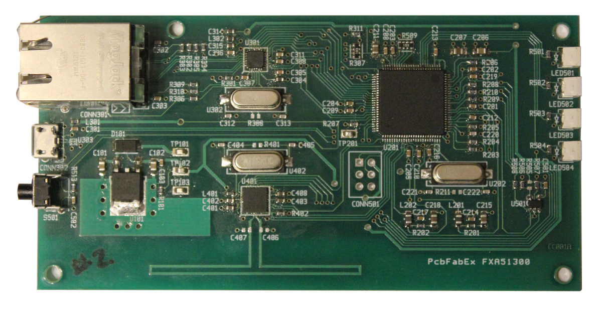
Our plan was to start with two devices: an internet-connected 802.15.4-to-Ethernet router and a 802.15.4 sensor. The router would send data to our webserver (this strategy prevented any issues due to firewalls). The 802.15.4 sensors would eventually be mesh-networked and would send their data to the internet through the router.
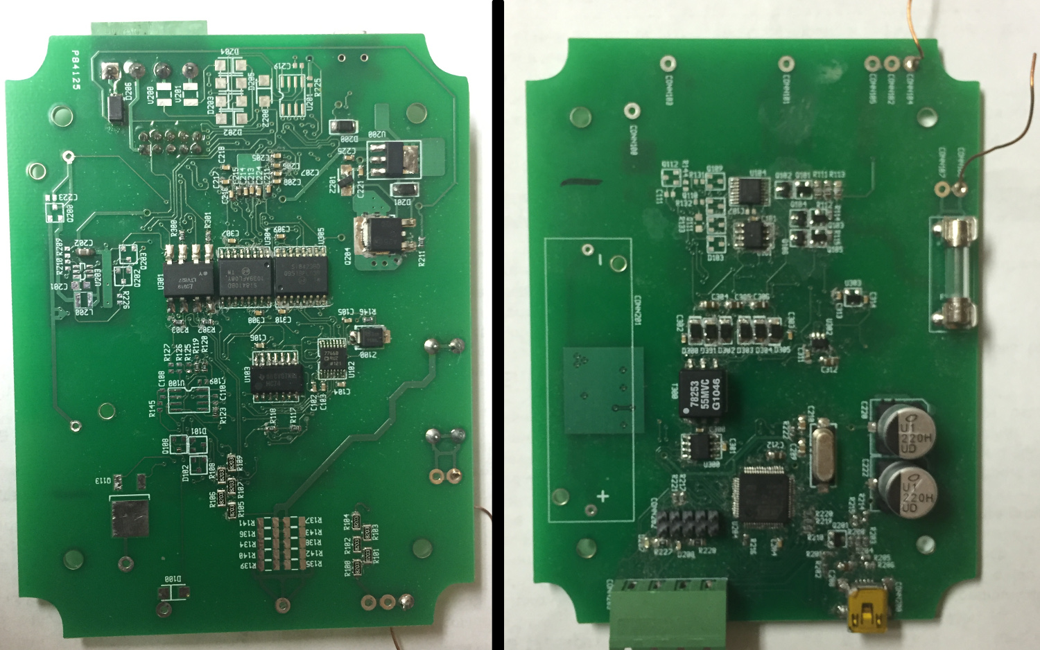
I took on the design of the CloudConnector router device. We chose to use a simple microcontroller in order to save cost. It would be very simple; it would grab packets and forward them to the server. It was built using an Atmel Cortex-M3 SAM3X processor. It had an Ethernet port, an 802.15.4 antenna, a few LEDs, and a reset pushbutton.
My dad and brother worked designed and built the TempSensor. It had an on-board thermistor, a coin-cell battery, and an Atmel ATMEGA128RFA1 (combination microcontroller and 802.15.4 radio). It was designed to be ultra low-power.
I also designed the cloud backend service called "CloudHandler." The CloudConnector connected to the CloudHandler service via TCP port 6201 and pushed the temperature sensor measurements. The CloudHandler service stored the messages into a MySQL database.
My website had a page to display the temperature sensor measurements. After everything was installed and working, you could visit our website to see the temperature in Platteville, WI, La Crosse, WI, and Minneapolis, MN.
Eventually, we decided that consumers wouldn't be interested in these wireless temperature sensors at the price point that we could hit. Without a different set of features, there wasn't enough incentive to buy the temperature sensors from us when there are very cheap wireless temperature sensors available from China.
EETool
In 2011, my brother and I looked at buying some electronics equipment but were disappointed at the high cost of multimeters and oscilloscopes. We wanted a USB-connected multimeter with some oscilloscope capabilities. After some research, we didn't find any of these available online, so we decided to build our own.
We designed a board that could measure voltage, current, and resistance. We supported measurements up to 1000 Volts, 10 Amps, and 10 megOhms. We designed the system to be software-controlled ranging with full auto-ranging support. The system connected to the PC via USB and was powered by USB.
Safety considerations were a large part of the design. We separated the communications and control section of the board from the analog section with an isolated DC/DC converter. The analog section used large trace spacings to give adequate creepage/clearance distance. Optocouplers were used everywhere that data needed to be transferred between the isolated and the control sections of the board.
The USB communication was handled through a USB CDC emulator and corresponding driver on the PC. The EETool appears on the PC as a serial device. I wrote a simple shell to parse commands and display data.
The system worked and we were able to take measurements. My brother used the multimeter on a school project when he needed to capture some circuit transient response curves.
Meshnet
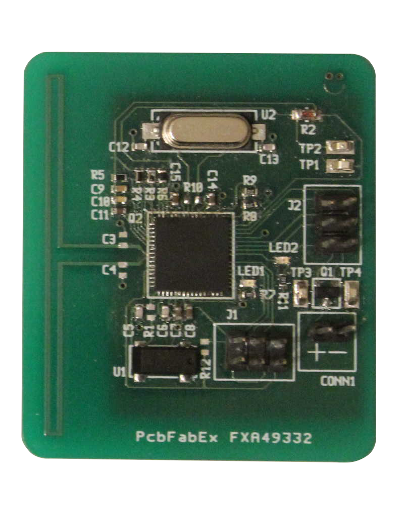
After building Wiremic, I wanted to try another, more advanced project. I had heard a lot about ZigBee, but I found that the ZigBee stack was large, complicated, and resource-intensive. I wanted to design my own simpler protocol that would use less power and work on smaller microcontrollers.
I designed the hardware over the summer of 2010. Towards the end of the summer, I started a blitz to get the hardware finished. Unfortunately, my brother and dad needed my help on a 48-hour road trip out to Idaho. We had a mattress in the back of our 15-passenger van, and I spent several hours on the trip sprawled out building schematic symbols and footprints. I got the hardware wrapped up and sent out for PCB printing before I went back to college.
This project taught me the importance of soldermask. I ordered the PCBs without soldermask to save money (I used the "Barebones" offer from Advanced Circuits). When the PCBs arrived, I had an enormously difficult time soldering the components. I had routed traces under my 0603 passive components, and the solder was forming bridges underneath my capacitors. I was able to get the boards working, but I have since vowed never to order boards without soldermask.
On this project, I also tried out a PCB-trace antenna. This was much cheaper than using a chip antenna. The antenna worked very well; I was able to get a few hundred feet of range.
The hardware was successful, and I began writing the FreeRTOS applications to run the radio. The radios worked, and I was able to transmit data between sensors.
Unfortunately, the software for this project became a much larger task than I had expected. I began to understand why the ZigBee protocol was as large as it was, and I eventually stopped work on the project due to other priorities.
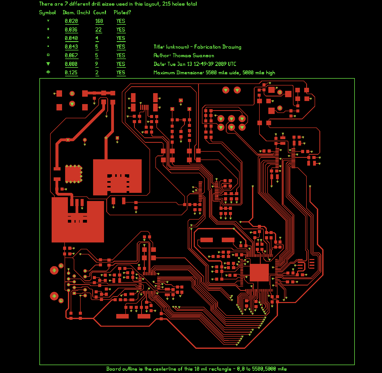
Wiremic and Wimic
During finals week in my freshman year of college, I became bored of classes and decided to try an engineering project. Having been a sound engineer at our church, I was frustrated by the poor quality of computer audio cards and the expense of running long XLR cables back to the sound booth.
I decided to build an Ethernet-connected audio card that digitized audio from an XLR microphone and pushed it into my Mac's Core Audio system. This allowed the audio to be fed into standard audio-editing platforms like Garageband.
I started the component selection and PCB design just as finals were wrapping up in December of 2008. I got advice from my Dad while working through the schematics (he helped me design the board-level power supply). I spent an 18-hour marathon night laying out the PCB and managed to order everything just before winter break was ending. I soldered it up, plugged it in, and had a working prototype after just a few weeks.
My board used an Atmel ARM7 processor with an Ethernet MAC peripheral. I used a programmable-gain amplifier to boost the amplitude of the microphone audio. I used a 24-bit external ADC to capture high quality audio. I used an external AC/DC wall-wart power supply and a board-level converter to get +5V, -5V, and +3.3V rails.
Not wanting to write my own TCP/IP stack from scratch, I searched and eventually found lwIP, a TCP/IP stack for embedded devices. I found that lwIP worked well with FreeRTOS, so I downloaded that and taught myself about RTOSes.
I wrote code in C to pull samples from the external 24-bit ADC, packetize them, and send them over the network to my Mac. I read the Core Audio API and wrote a driver to grab the ADC samples and inject them into the Core Audio system.
In the end, I was able to use this board with Garageband to record audio. The audio quality was much higher than I was able to get from my built-in soundcard, and the board could stream the audio to me over our wifi network.
Linux and Networking
In high school, I started configuring Linux servers and learning about networking and internet routing. I went through 6 Linux distributions on our home computer (Fedora, Arch, Slack, Gentoo, Ubuntu, and Debian).
In 2004 (age 14), I heard from a family friend about Linux. I read about it online and decided that I needed to try it and compare it to Windows XP. My dad was understandably hesitant and made me promise that I wouldn't lose any of the files. I bought a second hard drive, burned the install CD, and started the installation. After some phone calls to my friend about GRUB and the master boot records, I had a working installation of Fedora.
After installing Fedora, I found that Linux had very poor support for dial-up modems. Our computer had an internal soft-modem, and I tried everything to get it connected to our dial-up ISP. I compiled programs and drivers from source, re-configured and re-compiled my kernel, and did some extremely basic source code editing. I was never able to get the soft-modem working.
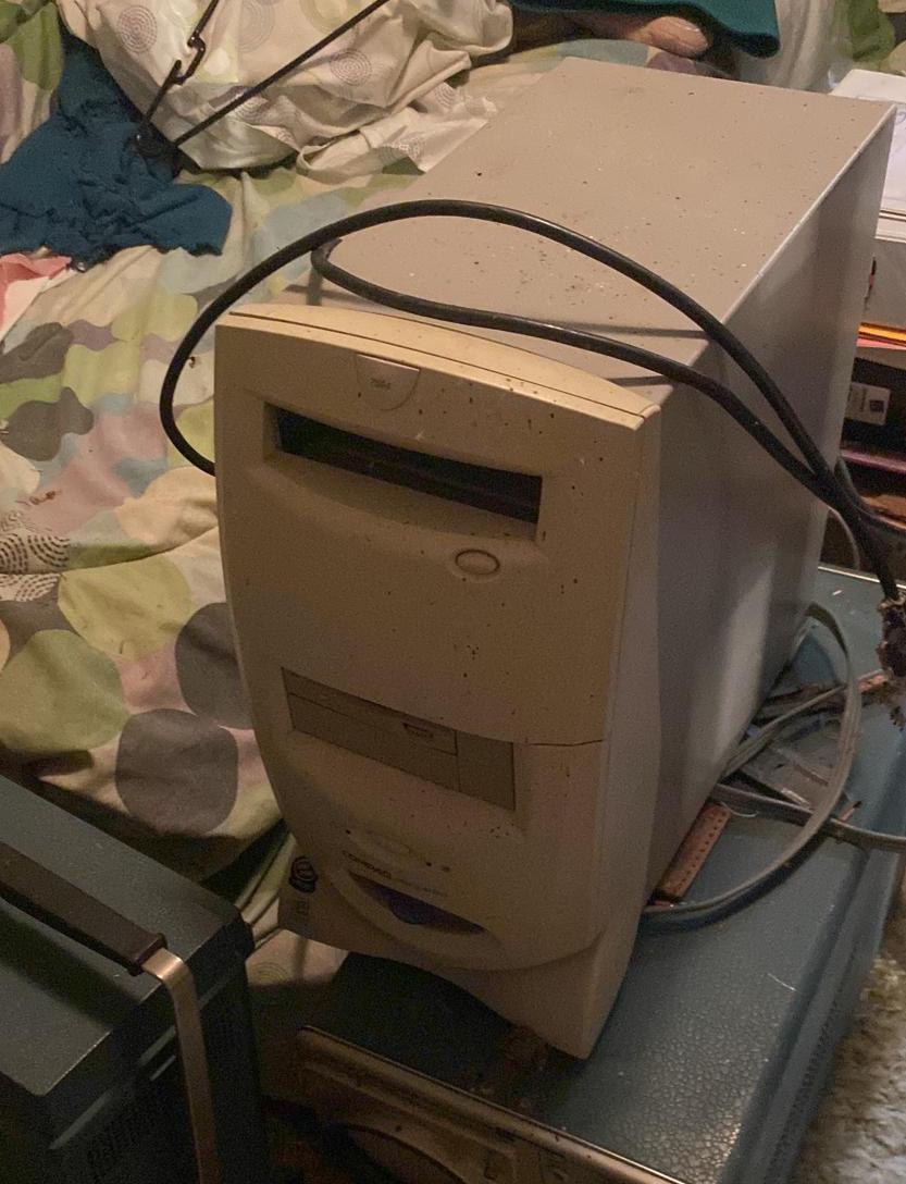
After failing with the soft-modem, I decided to install Linux on an old Windows 98 machine that we had in our basement. Since that machine didn't have many resources (7GB hard drive, 64Mb RAM, 600MHz Celeron processor) I installed command-line-only Slackware. Since my dad didn't want to run Ethernet cable down to our basement, I set up two WRT54-G routers in WDS-mode to connect the new server to the old computer. I shared the internet connection in Windows XP and allowed the server to connect to the internet whenever we were dialed in.
I set up an account with DynDNS (dynamic DNS service) and started running a website out of our basement. I taught myself about DNS, networking, web hosting, and Apache. I set up a bulletin board (phpBB) to let my friends have discussions on my website. Since the site was only available over dial-up, my friends would call me up and tell me to connect to the internet whenever they wanted to post.
Over the years, I have used this server to teach myself about NTP, SMTP, POP, IMAP, HTTP, HTTPS, SSH, DNS, SSL/TLS, kernel configuration, Linux development, networking, iptables, SAMBA, NFS, and many other technologies.
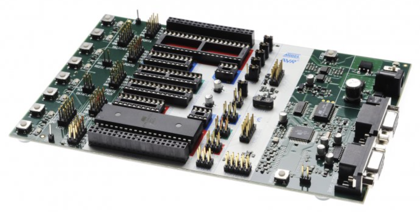
Atmel STK500 Development Kit
I taught myself assembly and C in middle-school. I programmed a few simple programs on the Atmel STK500 development kit using our Windows-98 PC.